![]()
MS1-Extra General Hardware manual
Only for use with the MS1 Extra code (MS1 - 68H908 based microprocessors)
By Philip Ringwood (daxtojeiro), James Murray (jsmcortina) and Ken Culver (muythaibxr)
|
MS1-Extra General Hardware manual Only for use with the MS1 Extra code (MS1 - 68H908 based microprocessors) By Philip Ringwood (daxtojeiro), James Murray (jsmcortina) and Ken Culver (muythaibxr) |
|
Before you start any hardware mods please read this entire manual and the Software Manual, available HERE. |
Warning
for
E-Bay buyers!! Please see the Official Suppliers list before buying through E-Bay. This is there for your protection. |
|
Please Note:
All of these instructions / diagrams are to be used at your own risk, like most things there is more than one way to do the same thing, what we have tried to do is to offer a method that we have tested or that others have tested for us. No warranty expressed or implied. Use at your own risk. |
Note if your TunerStudio dialogs do not match the examples in this document then you need to updated your setup file.
Please use this link to take you to the page with instructions on how to update your setup file.
Layout of MS PCB's for V2.2 -- for V3.0 -- for V3.57
Suggested points for Supplies for V3.0 PCBs -- Component
Pinouts -- Outputs 1,2,3 and 4 -- Shift
Lights -- Map Table Switching
Layout of the Megasquirt PCB's
V2.2 PCB:

Topside view of V2.2 pcb (these are green pcb's)

The V2.2 PCB has 4 spare connectors (X11 to X14) these can be used for various inputs and outputs for the following circuits as they are conveniently available on the 37pin DB connector:
X11 = pin 25 of 37pin db
X12 = pin 27 of 37pin db
X13 = pin 29 of 37pin db
X14 = pin 31 of 37pin db


The V3.0 PCB has 4 spare connectors (SPR1 to 4) these can be used for various inputs and outputs for the following circuits as they are conveniently available on the 37pin DB connector:
SPR1 = Pin3 of 37pin db
SPR2 = Pin4 of 37pin db
SPR3 = Pin5 of 37pin db
SPR4 = Pin6 of 37pin db
As can be seen, theres no proto area on the V3.57 and the components are very small. So soldering wires onto the board for spark outputs, hardware options, etc, is going to need a great deal of care. You may even have to remove some parts, which is not easily done to surface mount components, so I don't feel these manuals should cover doing this, as damage is very easy to do. Also a daughter board will need to be built if you want some of the hardware options as theres no proto area to build on. I have therefore assumed if you bought a V3.57 that you will not be modifying it to use the hardware functions such as Tacho out, PWM Idle valves, Boost control, Launch input, etc, etc. If you do wish to use these then you will have to build a daughter board of some form to mount the components on. If you use more than 2 spark outputs youll need to use the db15 connector, but ensure you strengthen the traces on the board with copper wire or solder to the pin directly, also connect the outputs in pairs of pins, as per the instructions HERE.
Note that the JS0 - JS11 pads are all electrically the same as the V3.0 PCB as are the SPR1 - 4 pads, so they can be used in the same way as the V3.0 PCB. The addition is JS12 wich is the same as the bottom of R1 on the V3.0 pcb, but R1 will still need to be removed to use it on the V3.57, so be very very carefull !!!

Suggested points for Supplies inside the V3.0 ECU


These outputs need a transistor circuit built on the prototype area to use them for any of the following options.

|
DigiKey part
numbers:
|
Farnell
part numbers
|
|
2N2222A = 497-2598-5-ND |
2N2222A = 920-7120 |
Controlling Outputs 1 and 2
These outputs are generally to be used to switch relays on and off that control various items, e.g. Cooling fan, Electric Power Steering Pumps, VVT valves, etc.

Please Note: To use Output 1 please set X4 (JS2) function in the Codebase and Outputs function settings to Output 1. This cannot be used with the Boost Controller as it uses X4.
In the above example the for Output1 you will see that it is selected to RPM, so when the engine RPM is above 2500 (25 Raw) the output will come on until the engine RPM drops 100 (1 raw) RPM below the setpoint. There is also an Upper Limit so in the same example if the RPM goes above 3500, (35 Raw) the output will go off until it comes under the Upper Limit again.
For temperatures you simply enter the degrees F +40, so in the above example Output 2 will turn on when the coolant temp is above 200 F (240 - 40F). The output will stay on until the coolant goes below 195F as it has a hysterisis of 5 (5F) There is no upper limit set so it wont turn off when above the setpoint.
The output can also be inverted, so it will effectively be OFF when it is ON, etc.
Controlling Outputs 3 and 4

Output 3 is Pin 15 of the uP (U1) when Output4 option in
set in the Codebase and Outputs , see the Software
Manual for more details on this. (Note: this can NOT be used if
you are using the output for Spark Control e.g. a 8cy wasted spark setup)
to connect this up, solder a wire to the top of R14 and connect it
as the wiring diagram. This output has the option for a delayed off. So once
it has trigger the output will only turn off after the time delay. This can
be used for what ever you want, the example uses DECEL to trigger the output
to a valve that drains off boost when the decel cuts in.
Output 4 is used if LED 18 is set to Output4 option in Codebase and Outputs , see the Software Manual for more details on this. (Note: this can NOT be used if you are using the output for Spark Control e.g. a 6cyl or 8cy wasted spark setup) . This can also be used for the coolant fan output, this allows you to run Water Injection on the X2 output and still use the coolant fan settings.
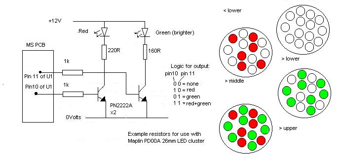
The shift lights allow either a single light, a Tricolor LED cluster or Sequential Shift Lights.
Please note the Sequential and the Tricoloured options can NOT be used when running with SparkE set as an output, see the Software manual. e.g. a 10cy or 12cy wasted spark setup. If you want to have a shift LED with a 10 or 12cy then see the final option (single light using Output1)

The shift Light settings can be found under the Outputs section.
In the above example the 2 outputs will come in this sequence:
| RPM | Output pin 10 (JS7 V3.0) | Output pin 11 (JS8 V3.0) |
| < 5800 | 0 | 0 |
| = 5800 | 1 | 0 |
| = 5900 | 0 | 1 |
| > = 6000 | 1 | 1 |
Wired up this way the outputs give you a formula 1 style sequential system.
YOU must find the correct resistor values for the LEDs you use.
Values shown here are for Maplin high brightness 10mm LEDs with IF 20mA
assuming 15V supply and forward voltage of 2V.

|
DigiKey part
numbers:
|
Farnell
part numbers
|
|
2N2222A = 497-2598-5-ND |
2N2222A = 920-7120 |
PLEASE NOTE: Pin 10 = JS7 on a V3 pcb and Pin 11 = JS8 on a V3 pcb
Tri-Coloured LED's:
 Maplin (UK Electronics Store) PD00A
Wired up this way the outputs give you a single cluster that changes colour.
Example circuit. NB. I haven't actually tested it yet.
YOU must find the correct resistor values for the LEDs you use.
Values shown here are for Maplin PD00A cluster Red IF=20mA, Green IF=40mA
assuming 15V supply and forward voltage of 10.5V (red), 8.4V (green).
Single light
If you don't like the above, just wire up the pin 10 circuit above and set the lower limit only.
Another option is to simply wire an LED to Output 1 (X4 JS2) using the transistor circuit above and select RPM, this can be set as a warning LED for coolant, RPM, etc. The Shift LED can be wires this way using Output1 as the set point.
Map Table Switching
This feature allow you to swap between two fuel, boost and spark maps while
driving. There are a number of possible applications for this - dual fuels,
street vs. open header race settings etc.
Extra hardware is required for a switched input to JP1 pin 6 (JS9 on a V3
pcb).
Choose one of the following input circuits:


|
DigiKey part
numbers:
|
Farnell
part numbers
|
|
2N2222A = 497-2598-5-ND |
2N2222A = 920-7120 |
Once
the circuit is fitted and tested then use the following options in
TunerStudio to select which tables you want to switch between:
To change Spark
Tables, go to Spark Menu, open Spark Table Selection:

Select Switch Tables to go from Spark Table 1 to Spark Table 2. Once one of this option is selected the Spark Table 2 will become active so you can then set the 12x12 Spark Table 2 up.
To change the VE Tables (Fuel tables), go to Advanced, Fuel Table Selections:
 Please note this switches between VE table 1 and 3, NOT VE Table 2, as VE2
is for Dual Table use.
Please note this switches between VE table 1 and 3, NOT VE Table 2, as VE2
is for Dual Table use.
To change between Boost Target Table's Select the Switch Boost Targets Table to "Targets 2" and this will use the Boost KPa Targets Table 2 when the input
JP1 pin 6 (JS9 on a V3 pcb) goes low.

The tacho output pin is for use where the car's original tacho signal would have come from the ECU, or it can be used to create a high voltage pulse where a conversion from a single coil setup to a wasted spark setup has been carried out and the original tacho signal came from the switched 12V side of the coil.
Due to the vast amount of tacho's out there it is very difficult to give a suitable diagram, but these have worked for several installation:

If the above examples don't work then try fitting a variable resistor in line with the tacho signal and adjust the pot untill it works:

Options for High Voltage tacho's (rev counters that were fed from the coils -ve)
Another option for Hi Voltage output to a rev counter (rev counters that were fed from the coils -ve)

|
DigiKey part
numbers:
|
Farnell
part numbers
|
|
2N2222A = 497-2598-5-ND |
2N2222A = 920-7120 |

Launch control works when the input (JP1 Pin4 for V2.2 pcb's
or JS11 for V3.0 pcb's) is switched low from a switch on the clutch or brake.
See HERE for a suitable circuit diagram, but
use JP1 pin 4 for V2.2 or JS11 for V3.0. It retards the ignition
to the setpoint when the RPM reaches the first limit, this reduces power
and helps to slow the engine down. Then it goes into Hard Limit when the
RPM reaches the Hard Limit setpoint. The style of hard rev limit
is set by the Rev Limiter Types.
The Launch Control also has the option of a Variable Launch hard
cut rev limit point. If its selected to ON in the setting screen then the
ECU stores the current engine RPM as soon as the input is switched and uses
that as its Hard Cut RPM setpoint. The switch must remain down untill the
launch has complete as it stores a new value every time the button is pressed.
This is to enable you to alter the setting at the track without having to
get the laptop out. We wouldn't recommend this with a clutch switch, as
every time you put your foot on the clutch it will take in the rpm and use
that as the limit, I would use a thumb switch or something similar as the
launch switch in this mode.
The flat shift settings are for use with a clutch switch and allow for different limits when changing gear, so you can keep the pedal down to maintain the power from the engine. If you press the clutch switch above the flat shift arming limit then the code uses the flat shift limits and retards the ignition and hard limits at the flat shift set points. Any lower than the arming rpm and it uses the launch limits. This is NOT recommended to be used when using the Variable Launch function. To disable, set the arming RPM above your maximum rpm.
The MS1 can only control idle valves using PWM (Pulse Width Modulation) this is generally valves that have 2 - 3 connections or it can control a switched valve, i.e. ON or OFF.
Please Note: Valves with 4 connections are usually stepper motors that MS1-Extra can not control.
The Ford valves and the Bosch valves used for testing have
a resistance of just under 1 ohm and pull about 1.2 amps when connected
directly to a 12V battery.
As standard the v2.2 Megasquirt uses a 2N2222A and the V3.0 uses a ZTX450.
These transistor's are fine as a driver to control a relay, as they have
a current rating of 0.8A, which is enough for a relay coil. This type of
idle valve would be a single open/closed style valve with no control over
how much air it lets in. But to drive a PWM idle valve directly (e.g. bosch
or Ford idle valve), you need a more powerful transistor. You have two options.
One is to use a ZTX650 or the tougher power darlington TIP122. ( I
have tested the ZTX650 and this transistor gets VERY hot as the valve's
current is very close to the transistor's limit, so if possible use the
TIP122 as this is more than capable)
Option 1 (ZTX650)
V2.2 PCB, remove Q5 and fit a ZTX650 instead (some kits included this as standard - check before replacing.) Remove R16 (1k) and fit a 510ohm resistor instead. Check D9 is in place.
V3.0 PCB, remove Q4 and fit a ZTX650 instead. Remove R39 and replace it with a wired link to short the position out, this connects the emittor straight to ground.

Option 2 (TIP122)
V2.2 PCB Remove Q5, solder in wires as below to remotely
mount the TIP122.
Fit a diode (IN4001) so the banded side is connected to 12V supply and the
non-banded side is connected to the collector of the TIP122

|
DigiKey part
numbers:
|
Farnell
part numbers
|
|
TIP122 = TIP122FS-ND |
TIP122 = 929-4236 |
V3.0 PCB Remove Q4, Q20, D8 and R39. replace R39 with a wired link or solder the (E) emittor to the right side of position R39 rather than at the Q4 position.
The TIP122 needs to be bolted to the case or the heat bus bar as below, but it MUST be insulated, so make sure you use a mica insulator like on the flyback transistors.
A IN4001 diode needs to be fitted across the output so the banded side of the diode is at 12V and the non-banded side is connected to the FIdle output. To do this either connect it externally at the valve (banded side to 12V supply and non-banded side to FIdle wire) or internally to the MS ECU:

Diagram of TIP122 wired into a V3.0 PCB. Note the Emittor (pink) connected to the right of R39. Also note that the TIP122 is where R37 should be. There's no need to install this and R38 if you wish to use these positions for other components like the TIP122. Simply link out these 2 positions with a wired link. (this can be seen on the above picture)
V3.57 PCB, this is a little tricky so care must be taken. Fit the TIP122 and solder a wire to the base of it and to the right side of R19, next to U8. Then connect the Collector to SPR1 (you can use any of the db15 pads if you wish) and the emittor of the TIP122 connect to a GND pad on the V3.57 pcb. This will give you the FIdle valve output on pin 3 of the db37 connector (or what ever connector the pad you used is connected to), do not use the standard FIdle output connector on pin 30 of the db37. The TIP122 can be mounted on the case or in place of R37 on the heatsink if R37 is linked out, remember it MUST be insulated!

2 Wired Valves
These valves are wired between switched 12v and the Megasquirt FIDLE pin.
Make sure the 12v is switched off when the megasquirt is off. Many looms
contain a protection diode, leave it there.
Some valves will have a spring return to shut them, others
have one to open them, so the duty cycle at hi and lo temps depends if the
MS ECU has to drive it open against the spring or shut against the spring.
If the ECU has to shut the valve down against the spring to reduce air going
through it as temp increases then the duty cycle will need to increase with
temp, so the value at low temp will be around 0 and the duty at higher temp
will be 100 or so. The opposite if the MS ECU has to force the valve open
against the spring to increase air flow.
3 Wired Bosch Valves (0280 140 505)
The bosch valves can also be made to work via the FIdle output, these need
the transistor mod as above and they need to be wired as the diagram below.
The centre pin goes to +12V, one of the other 2 pins will hold the valve
shut when its connected to ground (0V). This pin needs to go to earth via
the resistor, the other pin goes to the FIdle output on the DB37 connector.
On a 3 wired valve there are effectively 2 windings that fight
against each other, one opens the other closes it. So we put a resistor
in line to ground with one winding, this shuts (or opens it depending on
what winding you use) the valve, so its like having a spring holding it
one way. The MS ECU then forces it either shut or open, it can do this as
the resistor in the other winding limits how much it can force it one way.


Base settings for the bosch valve in Warmup Only mode:

Closed Loop Mode
The following are Jerry's comments (www.diyautotune.com)
on setting up open loop on his Miata.
"Some engines struggle to idle when an extra load is put on them,
such as with the A/C on, when you decel and come to a stop the engine struggles
to recover a stable idle and often stalls. The fix--- First of it looks
like you need a pot-type TPS for this which the 90-93 Miata doesn't have,
but later models do. In the idle control dashpot settings you set this up
so that when it sees the TPS go below a certain point, and the RPM drop
below a set point as well, it opens up the IAC a set DC%. Here are my settings
for my 95 Miata-- I can change these to disactivate it and immediately I
start stalling again, set them back like this and it settles to a nice stable
idle when I come to a stop with the AC on.

The TPS Threshold is in ADC-- you want it a bit below your lowest cruise TPS ADC, and above 'off throttle' ADC. The RPM setting is an addition to the interpolation of the fast and slow idle speeds above. So in this case fast is 1600, slow is 900-- so the interpolation is 1250. So by adding 500 to this we're telling it to activate when the RPMs fall below 1750rpm and the TPS is below 50 ADC. The Dashpot settle time has to be tuned a bit, too slow and it doesn't react fast enough, too fast and it gets into a funky oscillating idle loop and doesn't settle in right. 43-55 seems about right on my car, I'm still playing with this one. Dashpot adder DC is the DC% to add when this gets activated-- so we're adding 2% DC to the IAC when the TPS and Idle drop below these points. You can set it to 5% and watch it idle up really high when you come to a stop with the AC off, then settle down. 2% DC seems about right for me. It drops to about 1000 rpms, takes one tiny little bounce of like 100rpm, and then settles nicely."
Other Idle Valves
There are valves that need no control other than a 12V supply
when the ignition is on. These heat up a bi-metalic strip that rotates a
plate inside the valve and shuts the air down as the engine heats up, these
are known as Extra Air Valves. They are becoming rare and hard to get old
of, they were fitted to various engines, like the Flapper type RV8 EFI's.
The Idle Speed has to be controlled with the throttle stop when using these
type of valves, as the valve is only used to add air when the engine is
cold.
Here is a Bosch example:


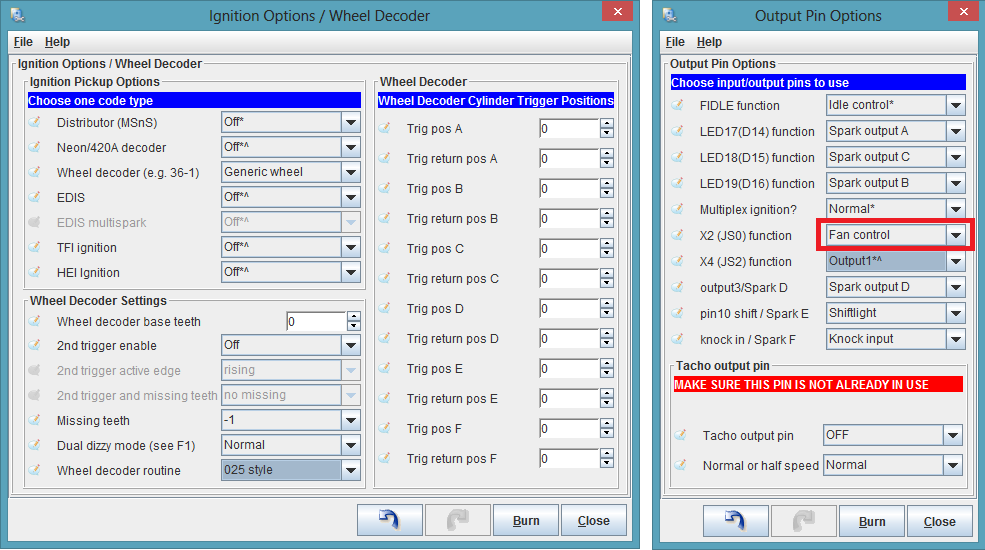
This feature allows control over a water injection pump and a fast acting valve. Please note this cannot be used if you select X2 (JS0) as fan control in Codebase and Outputs (see below):

|
DigiKey part
numbers:
|
Farnell
part numbers
|
|
2N2222A = 497-2598-5-ND |
2N2222A = 920-7120 |
The output X3 (JS1 for a V3 pcb) is driving a FET which in turn switches the fast acting valve from Aquamist (PtNo 806 244).
Please note: Whilst the water injection pump is on the O2 sensor is ignored (open loop mode), as the water would upset the readings.

The settings for Water Injection can be found under the Advanced menu:

When the manifold boost level (detected by the MAP sensor)
and engine RPM are above the set values in TunerStudio and the Manifold Air
Temperature is above the set value, the Pump is turned on via X2 for a V2.2
pcb or JS0 for a V3 pcb. X3 (JS1 for a V3 pcb) is pulsed at the same rate
as injector CH #2 (this can be used to drive a fast acting solenoid). The
theory being that if a water nozzle is selected to give a 15% flow rate
of the total of the injectors flow rate then it follows that it should naturally
give the right amount of water. So if your total injector flow is 2000cc/min
(all of your injector flow rates added together) then a 300cc/min nozzle
would give you 15% water to fuel ratio, which is a good starting point.
i.e. 15% of 2000cc of fuel = 300cc of water.
The Manifold Air Temp is ignored once the water has turned on as this should
reduce virtually straight away with the water evaperating in the air. The
water system doesn't turn off again untill boost pressure or RPM has dropped
below the set levels.
Constant Barometric Correction
When using the original map sensor for Manifold Pressure (Speed Density mode) you can gain constant barometric correction by fitting the same type of sensor to the input X7 (JS5 V3.0), it MUST be the same type as the main MAP sensor though!!

|
DigiKey part
numbers:
|
Farnell
part numbers
|
|
0.22uF Cap = P10971-ND |
0.22uF Cap = 389-1215 |
If you're using Alpha-n mode (NOT HYBRID ALPHA_N) then you can use the MAP sensor that's already on the MS board as a constant barometric correction sensor, but don't connect it to the manifold, simply leave it vented to atmosphere. In this case Select:

Please Note: This feature is only suitable for use if your spark map is controlled by MS. E.g. MSnS, Edis, Neon, etc.
The MS ECU doesn't detect knock straight from a Knock Sensor, we need a amplifier / filter unit that gives a digital signal (5Volts hi or 0Volts lo) when knock is present onto pin 5 of JP1 for a V2.2 or JS10 for a V3.0 PCB. We, therefore, highly recommend you buy a pre-built knock amplifier / tuned filter from HERE, but if you prefer you can build this circuit, but this is NOT a tuned circuit, so setting it up can be a little difficult:

|
DigiKey part
numbers:
|
Farnell
part numbers
|
|
2N2222A = 497-2598-5-ND |
2N2222A = 920-7120 |
The settings for the Knock Detection system can be found under Spark.

As long as the engine rpm is below the setpoint and the MAP
KPa is below the setpoint then it will do the following:
If a knock is detected (JP1 HEADER Pin 5 goes low on the V2.2 pcb or JS10
on the V3 pcb's goes low) the ignition will retard by the first knock amount.
Any more knocks are ignored untill the Wait Time has passed. If it receives
another knock it will add a retard by the Subsequent Value and wait till
the timer (Wait Time) has passed. If no knocks are found it will advance
by the Advance amount and wait till the timer runs out before adding some
more advance. If it receives any knocks during the advancing stage it will
immediately retard and restart the timer. There is a max Retard Allowed
setting so it can be pegged. There is also a built in limit of 30Deg Retard
allowed, I can't see that being a problem.

This feature allows all fuel calculations to run from an in-line Mass Air Flow Meter rather than the MAP sensor. The sensor needs to have a 0-5V output voltage, it MUST NOT have a larger output voltage than 5V. Ford sensors seem to be compatible with this but please check before you connect it to your MS.
Sensors tested so far:
Ford F1ZF-12B579-AA AFH55-03B

|
DigiKey part
numbers:
|
Farnell
part numbers
|
|
2K2 resistor = 2.2KQBK-ND |
2K2 resistor = 543-469 |
To set the ECU up to use MAF rather than MAP you need to find the Advanced Code Options in the Basic / Load Settings menu.

The MAF input must be connected to X7 for a V2.2 PCB or JP5 for the V3.0 PCB. As most MAF's have a built in compensation for air density it is best to select Air Density Correction - Built into AFM, this sets the air density value in the fueling algorithm to 100.

To change the Control Algorithm to "Air Flow Meter" select it from the option in the Fueling Algorithms drop down menu (highlighted RED), then click ok to save your changes and exit the project properties dialog. Upon exiting your project will reload automaticly with the changes you have made.

In order to see the correct dials in TunerStudio that correspond to the MAF sensor then open the MSnS_Extra.ini file in a text editor from C:/programfiles/Megasquirt/TunerStudio/mtCfg/ and search for : "MAFGauge" you will find:
;Gauge Setup 5 Alpha-N / MAF
; gauge1 = tachometer
; gauge2 = tpsADCGauge
; gauge2 = MAFGauge
Change this to:
;Gauge Setup 5 Alpha-N / MAF
; gauge1 = tachometer
; gauge2 = tpsADCGauge
gauge2 = MAFGauge
To log the voltage from the MAF, open the MSnSExtra.ini file from C:/proramfiles/TunerStudio/TunerStudio2.25b/mtCfg/ and search for : "MafVolts" you will find:
entry = advSpark, "Spark Angle", int, "%d"
entry = egttemp, "EGT", int, "%d"
; entry = fuelpress, "Fuel Press", int, "%d"
entry = KnockDeg, "Knock", int, "%d"
; entry = XForce, "X GForce", float, "%.2f" ; X on X7
; entry = YForce, "Y GForce", float, "%.2f" ; Y on X6
; entry = MAFVolts, "MAF Volts", float, "%.2f" ;
MAF on X7
Remove the semicolomb from in front of entry = MAFVolts and place a semicolomb in front of entry = egttemp:
entry = advSpark, "Spark Angle", int, "%d"
;entry = egttemp, "EGT", int, "%d"
; entry = fuelpress, "Fuel Press", int, "%d"
entry = KnockDeg, "Knock", int, "%d"
; entry = XForce, "X GForce", float, "%.2f" ; X on X7
; entry = YForce, "Y GForce", float, "%.2f" ; Y on X6
entry = MAFVolts, "MAF Volts", float, "%.2f" ; MAF
on X7
This feature gives you control over nitrous oxide injection (N20). At the simplest level it can ensure that a typical nitrous system is only activated about certain rpm etc. If you want to be more advanced you can retard the timing or switch to a new fuel and/or spark map when the NOS is activated.

|
DigiKey part
numbers:
|
Farnell
part numbers
|
|
2N2222A = 497-2598-5-ND |
2N2222A = 920-7120 |
Basically this system gives a signal out on X3 V2.2 PCB (JS1 on a V3.0 PCB) to enable the NOS sytem when certain setpoints have been met. This can be used to switch on your NOS, if the system is armed or you can use a pressure switch which if it is made and the WOT switch is made then there will be an input onto pin 6 of JS1 (JS9 on a V3.0). The input can then be used to add fuel, retard ignition or to change the maps over. (Switching Fuel and or Spark Maps)
This system can add the extra fuel for use with nitrous and it can retard the ignition by a preset amount when it is activated. Spark table2 can be used with nitrous . Fuel VE table3 can be used with nitrous if you so desire to use it. If you don't want to switch over tables then ensure the boost, spark and fuel table selections are set to not switch over! See the Table Switching Notes in the MSnS Software Manual
NOTE: THIS SYSTEM DOES NOT ADD FUEL OR RETARD THE IGNITION
UNTILL IT RECEIVES A LOW SIGNAL ON THE NITROUS CHECK BACK SIGNAL
(JP1 Pin 6 for V2.2 pcb's or JS9 for V3.0 pcb's)
This is so you can arm the system in the cockpit and run the signal through
pressure switches, etc.

Additional Fuel PW is calculated by interpolating between the user setpoints, so if you set the Turn N20 on at 3000 rpm and the NOS Max RPM to 6000 then the additional fueling will be interpolated between 3000 and 6000rpm. The amount of fuel added should reduce with engine speed as the same amount of NOS will be added at 3000 as at 6000, but more fuel will be added as there are more squirts of fuel at 6000. If you don't want to add extra fuel, due to having a wet setup, then simply set the Additional Feul PW's to ZERO as above. The O2 correction is turned off during the time the system is active.
IMPORTANT NOTE: If Duty Cycle goes above 90% the NOS System will be turned off (X3 or JS1 output will go low), this is for safety reasons. The additional fuel and retard will also be turned off, the system will reset when either rpm or throttle position are brought back under the set points.
CAUTION: The system will add fuel every squirt, so calculations would need to take into account that you may be squirting more than once per Engine Cycle!!! PLEASE BE VERY CAREFUL - MELTED PISTONS ARE EXPENSIVE!!
The NOS output can be delayed to come on after a flat shift or a launch so it doesn't cut in during that time.
If in Dual Table mode you can select which Bank to add the enrichment PW to.
Turbo Anti-Lag can be used when NOS is selected and the ECU receives a low input on the NOS Check Back Pin6 JP1 (JS9 on a V3.0) BEFORE it turns the NOS output on X3 (JS1 on a V3.0) then this will enable the NOS Turbo Anti-Lag. So if the MAP is between the KPa limits then the NOS output will turn on. This system is used to spool the turbo up between a certain KPa range using NOS.
Second O2 Sensor and Dual Table

|
DigiKey part
numbers:
|
Farnell
part numbers
|
|
5.1V Zener = 1N5231BDICT-ND |
5.1V Zener = 931-767 |
A second O2 sensor can be connected to X7 V2.2 (JS5 for a V3.0 PCB) this cannot be used with the EGT logging circuit as it uses the same ADC.
It is important that the same type of sensor is used for both O2 inputs!
This allows injector bank#2 (output pins 34-35) to have a seperate EGO Correction compared to inj bank#1. This is only available in Dual Table as it uses the ego corrections, from the Fuel Table2 enrichments page to control the EGO for bank 2.
EGO for Bank 1 is still controlled by Fuel Table1's Exhaust
Gas Settings, the Injector Bank 1 is fired with reference to VE1 Table.
EGO for Bank 2 is still controlled by Fuel Table2's Exhaust Gas Settings,
the Injector Bank 2 is fired with reference to VE2 Table.
To enable Dual Table go into Fuel Settings - Fuel Table Selection - set Use table to 2(DT). Once this is selected you must then set the Constants2 (DT) and the VE table 2 (DT) and if using the second O2 input for EGO correction then you must set the Exhaust Gas Settings.
 |
|
Important: If using the second O2 sensor for correcting the second Injector Bank then it is HIGHLY recommended that VE table 2 is set EXACTLY as the VE table 1 unless you really know what you are doing!!
Exhaust Gas Temperature (EGT) Logging
This feature cannot be used with the second O2 sensor input
as it uses the same ADC. It allows you to display and/or log Exhaust Gas
Temperature. The code does nothing with the data to adjust engine parameters
- it is just a logging feature.
We now have 2 cicuits to chose from as we have re-designed the circuit a
little (change the top 10K resistor to a 15K) to allow a higher temperature
reading. Please see notes below if using the 0-1250C
(0-2280F) circuit. You need to build ONE of the following circuits:


|
DigiKey part
numbers:
|
Farnell
part numbers
|
|
1nF Cap = 495-1091-ND |
1nF Cap = 389-0934 |
To View the EGT gauge in TunerStudio right click on any gauge while TunerStudio is running and select the EGTGauge.
If using the 1250C drawing then you will need to edit
the msns-extra.ini file to read it correctly as the file is default to read
0-1000C.
So to read 0-1250C do the following:
Find the "msns-extra.ini" in "C:\Program Files\MegaSquirt\TunerStudio2.25\mtCfg".
Open the file in a text editor, e.g. Notepad
Search for this section:
#if CELSIUS
egttemp = { egtADC * 3.90625 } ; Setup for converting 0-5V = 0 - 1000C
#else
egttemp = { egtADC * 7.15625 } ; Setup for converting 0-5V = 0 - 1832F
#endif
change it to the following:
#if CELSIUS
egttemp = { egtADC * 4.90196} ; Setup for converting
0-5V = 0 - 1250C
#else
egttemp = { egtADC * 8.949 } ; Setup for converting
0-5V = 0 - 2283F
#endif
Now the readings will be 0-1250C or 0-2283F, depending on if your settings of C or F
Boost Control
This system is used to control the boost pressure from a turbo via a fast
acting valve on the waste gate, but it is still EXPERIMENTAL and must
be used with caution!

|
DigiKey part
numbers:
|
Farnell
part numbers
|
|
10K resistor = 10KQBK-ND |
10K resistor = 543-627 |
To use the Boost Controller please set X4 (JS2) function in the Codebase and Outputs function settings to Boost. This cannot be used with Output 1 as it uses the same pin X4. See the MSnS-Extra Software Manual for more info on this. A TPS is needed for this function to work.

The Solenoid PWM rate is the pulse width that is used
to control the solenoid, this will need to be experimented with to get your
system to react best to the controller.
The Controller Update is how often the ECU will look at the boost pressure and adjust the setpoint in mSecs.
The Proportional Gain is how hard it seeks the target.
Differential Gain means how it will react to sudden changes, it's roughly a predictive term, but for best results it probably has to be kept to a small value. Tune proportional first, leave differential for later
The Increase Voltage is for setting the valve so it operates the right way, generally as PWM Increases the Boost Increases.
Switch Boost Target Tables can be used when the Table Switching circuit is installed (see HERE) this simply switches between 2 target KPa tables.
Closed Loop KPa limit is the amount of boost difference allowed between the 6x6 Target KPa table and the actual boost value (MAP). E.G. if this is set to 50KPa then as long as the target was within 50KPa of the actual MAP KPa the ECU will continue to run closed loop (i.e. adjusting the PWM to try to get to the target value). Once the difference goes over 50KPa then the 6x6 Target KPa table is ignored and the 6x6 Boost Duty Cycle Table is used to calculated the PWM rate.


If
you have a question, comment, or suggestion for this FAQ, e-mail Phil
or James or post it on the
forum.
No part of this manual may be reproduced or changed without written permission from Philip Ringwood, James Murray, Ken Culver and Lance.
Many thanks to Lance for giving us permission to edit and adapt his MS Manual for MSnS-Extra use.
©2004, 2005 Bruce Bowling and Al Grippo. All rights reserved.
