MS3 expander flyback circuit... aint good enough.

Testing and development of Megasquirt 3

Moderators: jsmcortina, muythaibxr

Post Reply
y8s
Master MS/Extra'er
Posts: 478
Joined: Wed Jan 07, 2009 3:21 pm

MS3 expander flyback circuit... aint good enough.

Post by y8s »

I wanted to post this here for completeness and posterity and the community. I discovered I had a problem with this when I started testing the VVT code
(see this post: http://www.msextra.com/forums/viewtopic ... q3#p279479 )

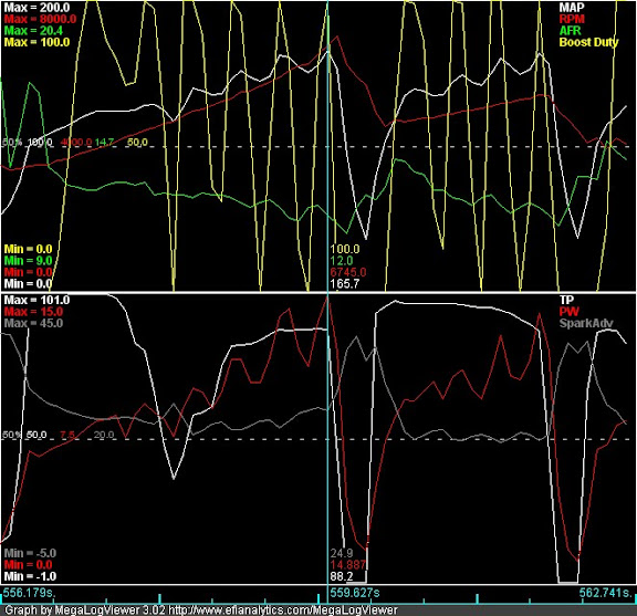
Well guess what? This morning I went to start my car (which was fine last night) and the idle and tach both went nuts. The idle increased to 4000 rpm randomly (duty cycle did not increase) and the tach needle started flipping around.

I had to drive to work and thankfully things remained almost normal. The idle valve became VERY noisy (still set at same 383 Hz) but managed to do ok.

When I got home tonight, I pulled my MS3x and noticed a rattle inside the case. I opened it up and found this:

Image

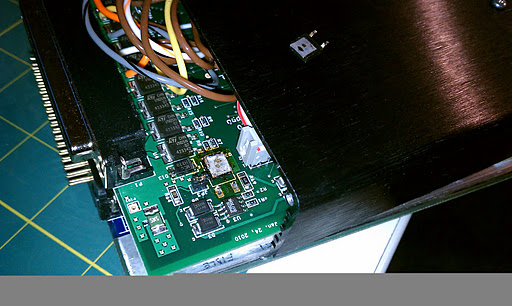
That is Q3 after having fallen out of the box. Apparently it was dumping so much flyback to ground it got hot enough to melt its own solder.

This is WITH a diode soldered from the VVT output to the +12V pins on the ribbon cable.

Tonight I re-attached the transistor and moved the +12V side of the diode to the S12 pad. The transistor must still be OK because when I reinstalled the box in my car, the car started up and idled fine--no more loud idle valve.


So now I guess I'm curious what to do about this. It seems that the expander board flyback circuit is insufficient to use even 4 of the 6 outputs it's designed to handle. I don't mean that to sound alarmist but it's a pre-built board and not something I can easily "beef up" for my application (which isn't so out of the ordinary--see below).

The outputs I use on the expander are: VVT, Tacho, Boost, and Idle (all doing exactly those things--which sort of drives my previous point home).

I want to make it clear that I'm not at all unhappy with the overall MS3x experience. I just want the product to get better.
racingmini_mtl
Super MS/Extra'er
Posts: 9130
Joined: Sun May 02, 2004 6:51 am
Location: Quebec, Canada
Contact:

Re: MS3 expander flyback circuit... aint good enough.

Post by racingmini_mtl »

You mention you're using 383Hz for idle. Which frequency are you using for the other outputs? Do you have a diode on outputs other than VVT?

I can't do anything about the board or its design but I'm curious to see what would be causing this.

Jean
jbperf.com Main site . . . . . . . . . . . . . . . . . . . . . . jbperf.com Forum
Image
jsmcortina
Site Admin
Posts: 39618
Joined: Mon May 03, 2004 1:34 am
Location: Birmingham, UK
Contact:

Re: MS3 expander flyback circuit... aint good enough.

Post by jsmcortina »

y8s wrote:This is WITH a diode soldered from the VVT output to the +12V pins on the ribbon cable.
As I mentioned before, I think that original diode placement you used is really poor as it is dumps the flyback energy into the Megasquirt power supply circuit. The diodes in the input circuit prevent it from recirculating through the valve (which is what you want.) So I'll be interested to see what difference it makes with it connected as you have it now.

James
I can repair or upgrade Megasquirts in UK. http://www.jamesmurrayengineering.co.uk

My Success story: http://www.msextra.com/forums/viewtopic ... 04&t=34277
MSEXTRA documentation at: http://www.msextra.com/doc/index.html
New users, please read the "Forum Help Page".
elaw
Super MS/Extra'er
Posts: 2926
Joined: Fri Oct 16, 2009 6:20 am
Location: Wilmington, MA

Re: MS3 expander flyback circuit... aint good enough.

Post by elaw »

One trick I used on the idle valve on my car is to put a diode right across the wires where they go into the connector for the device. That keeps the recirculation current path as short as possible, and keeps that current out of the Megasquirt entirely.
Eric Law
1990 Audi 80 quattro with AAN turbo engine: happily running on MS3+MS3X
2012 Audi A4 quattro, desperately in need of tweaking

Be alert! America needs more lerts.
y8s
Master MS/Extra'er
Posts: 478
Joined: Wed Jan 07, 2009 3:21 pm

Re: MS3 expander flyback circuit... aint good enough.

Post by y8s »

racingmini_mtl wrote:You mention you're using 383Hz for idle. Which frequency are you using for the other outputs? Do you have a diode on outputs other than VVT?

I can't do anything about the board or its design but I'm curious to see what would be causing this.

Jean
I'm using 383 Hz for Idle and VVT (I'd rather run 500 for idle and 300 for VVT but they are inextricably linked due to hardware design)
I'm using 39 Hz for boost
and whatever Tacho is is fixed in the firmware.

No other diodes.

---

I understand that I could run diodes across all of my loads to squelch the flyback but I'd rather not start cutting into OEM harnesses if I don't have to.

James: so far moving the +12 side of that diode to VVT has had no ill effects. Everything seems to work as it did before. I guess time will tell if it's an improvement or not.

On this note, since I can't trace the path of the +12V wires in the ribbon cable due to lack of schematics for the MS3 daughtercard, DO they actually go through any circuits other than returning to the main board 12 volt supply?

---

Update on my situation: I resoldered Q3 in place and moved the diode as mentioned above and put it all back together and the car works normally. It got me to work just fine.
jsmcortina
Site Admin
Posts: 39618
Joined: Mon May 03, 2004 1:34 am
Location: Birmingham, UK
Contact:

Re: MS3 expander flyback circuit... aint good enough.

Post by jsmcortina »

12V on the MS3 header connects to the 12V pin on the DIP40, but that places it downstream of D10 on the mainboard so it cannot be used for flyback wiring.
S12 on the other hand is raw 12V and is the correct place for flyback.

James
I can repair or upgrade Megasquirts in UK. http://www.jamesmurrayengineering.co.uk

My Success story: http://www.msextra.com/forums/viewtopic ... 04&t=34277
MSEXTRA documentation at: http://www.msextra.com/doc/index.html
New users, please read the "Forum Help Page".
jsmcortina
Site Admin
Posts: 39618
Joined: Mon May 03, 2004 1:34 am
Location: Birmingham, UK
Contact:

Re: MS3 expander flyback circuit... aint good enough.

Post by jsmcortina »

To add to that, I didn't read fully your (long ago) first post about your mod, so didn't spot the 12V connection problem with it.

In any case, from reviewing the MS3X schems, there's no need to add an additional diode, but instead solder a wire from the right of D1 (marked C) and run that to S12.

James
I can repair or upgrade Megasquirts in UK. http://www.jamesmurrayengineering.co.uk

My Success story: http://www.msextra.com/forums/viewtopic ... 04&t=34277
MSEXTRA documentation at: http://www.msextra.com/doc/index.html
New users, please read the "Forum Help Page".
y8s
Master MS/Extra'er
Posts: 478
Joined: Wed Jan 07, 2009 3:21 pm

Re: MS3 expander flyback circuit... aint good enough.

Post by y8s »

I see the 6 1n4001 diodes that head to the flyback circuit. I will move the S12 jumper to the cathode of one of those since they all seem to meet. Plus it saves me like 4 cents in components.
jsmcortina
Site Admin
Posts: 39618
Joined: Mon May 03, 2004 1:34 am
Location: Birmingham, UK
Contact:

Re: MS3 expander flyback circuit... aint good enough.

Post by jsmcortina »

y8s wrote:I see the 6 1n4001 diodes that head to the flyback circuit. I will move the S12 jumper to the cathode of one of those since they all seem to meet. Plus it saves me like 4 cents in components.
I'm interested to see the results - test criteria I'd be watching for:
- good valve control
- no component overheating
- no resets or other interference on engine operation

_If_ you score well on all three points then we can consider adding that jumper wire to the manual as a recommendation.

James
I can repair or upgrade Megasquirts in UK. http://www.jamesmurrayengineering.co.uk

My Success story: http://www.msextra.com/forums/viewtopic ... 04&t=34277
MSEXTRA documentation at: http://www.msextra.com/doc/index.html
New users, please read the "Forum Help Page".
y8s
Master MS/Extra'er
Posts: 478
Joined: Wed Jan 07, 2009 3:21 pm

Re: MS3 expander flyback circuit... aint good enough.

Post by y8s »

I will keep you all posted.

Also I did have good valve control without Q3 attached. :)
shuiend
Helpful MS/Extra'er
Posts: 71
Joined: Thu Jul 03, 2008 3:17 pm

Re: MS3 expander flyback circuit... aint good enough.

Post by shuiend »

Below is what my Q3 looks like. I am running the VVT code in my miata with only the diode going across the signal wire and the power. I have about 1500 miles on it and Q3 still looks fine. I still ran a wire from D1c to S12. I am not running any idle control.
Image
94 Miata running a MS3. Begi turbo kit with a SR20 t25
y8s
Master MS/Extra'er
Posts: 478
Joined: Wed Jan 07, 2009 3:21 pm

Re: MS3 expander flyback circuit... aint good enough.

Post by y8s »

jsmcortina wrote:
y8s wrote:I see the 6 1n4001 diodes that head to the flyback circuit. I will move the S12 jumper to the cathode of one of those since they all seem to meet. Plus it saves me like 4 cents in components.
I'm interested to see the results - test criteria I'd be watching for:
- good valve control
- no component overheating
- no resets or other interference on engine operation

_If_ you score well on all three points then we can consider adding that jumper wire to the manual as a recommendation.

James
James,
I'm digging this thread back up because I think adding this diode broke my boost control. I had to remove the solenoid because voltage was "leaking" back into my MS from the (somehow powered) boost solenoid and through the flyback diode I added and supplying just a little bit of juice to S12 and draining my battery...

I moved the 12V source and reinstalled the boost control solenoid and spent tons of time trying to re-tune it (original numbers caused horrible oscillation). I have since gotten NOWHERE and still have ridiculous boost oscillation at any PID values and I just realized THIS DIODE is the one thing that's definitely changed since it worked.

So when you say "good valve control", does the boost valve count?

Because it sucks.

I suppose a test would be to run boost control to a spare injector output on the expander?

Matt
jsmcortina
Site Admin
Posts: 39618
Joined: Mon May 03, 2004 1:34 am
Location: Birmingham, UK
Contact:

Re: MS3 expander flyback circuit... aint good enough.

Post by jsmcortina »

One test you could try this is to install the 1N4001 (or equiv.) across your VVT solenoid and remove that jumper wire. In that case your boost solenoid will be back to a 36V clamp and the VVT will have the 1.1V clamp.

James
I can repair or upgrade Megasquirts in UK. http://www.jamesmurrayengineering.co.uk

My Success story: http://www.msextra.com/forums/viewtopic ... 04&t=34277
MSEXTRA documentation at: http://www.msextra.com/doc/index.html
New users, please read the "Forum Help Page".
y8s
Master MS/Extra'er
Posts: 478
Joined: Wed Jan 07, 2009 3:21 pm

Re: MS3 expander flyback circuit... aint good enough.

Post by y8s »

yeah I'll give that a try.
y8s
Master MS/Extra'er
Posts: 478
Joined: Wed Jan 07, 2009 3:21 pm

Re: MS3 expander flyback circuit... aint good enough.

Post by y8s »

I'm adding the 1N400X from the cathode sides of the Expander's outputs for Idle and VVT to S12. Doing both because I don't want to retune them.

I'm going to plop my original boost settings back in and see how it works tomorrow.

Matt
y8s
Master MS/Extra'er
Posts: 478
Joined: Wed Jan 07, 2009 3:21 pm

Re: MS3 expander flyback circuit... aint good enough.

Post by y8s »

Boost response with the supplemental flyback wire described above between the cathode side of the expander outputs and S12:

Image


Boost response with that disconnected at the outputs side and moved to the cathode side of two diodes independently connected to the VVT and Idle outputs:

Image


Same exact boost settings.
braineack
Experienced MS/Extra'er
Posts: 287
Joined: Wed Oct 17, 2007 11:55 am

Re: MS3 expander flyback circuit... aint good enough.

Post by braineack »

I wonder if that's due to the cathode sides of all the diodes going back to Q3 and that transistor circuit. I'm thinking it would work fine if that was pulled from seeing 12v, so only d1-6 see 12v and q3 is removed from the circuit.
1991 Boosted Miata Running MS3 + MSX w/Full Seq.
https://www.trubokitty.com
redrider706
MS/Extra Newbie
Posts: 14
Joined: Mon Dec 07, 2009 8:32 pm

Re: MS3 expander flyback circuit... aint good enough.

Post by redrider706 »

What is the recommended way to fix the flyback issue for VVT setups?

Thanks.
-Raj
y8s
Master MS/Extra'er
Posts: 478
Joined: Wed Jan 07, 2009 3:21 pm

Re: MS3 expander flyback circuit... aint good enough.

Post by y8s »

the best solution is to put a diode across the VVT +12 and MS3X output.

You can do the same thing electrically inside the box by connecting the stripe of a 1N4007 to S12 (NOT S12C) and connecting the other side of the 1N4007 to the NON-stripe side of the diode of the output you're using. It'll be D1-D6 on the MS3X.

D1 Nitrous2
D2 Boost
D3 VVT
D4 Nitrous1
D5 Idle
D6 Tacho

For what it's worth, I also connected my Idle output to a second diode to S12.

And because I get easily frustrated with silly stuff, I put a connector on the S12 wire so I can separate the two boards from each other. :)
Post Reply