New dual VR board V2.0

A forum for discussing the MegaSquirt related (but non-B&G) board development, assembly, installation, and testing.

Moderators: jsmcortina, muythaibxr

racingmini_mtl
Super MS/Extra'er
Posts: 9130
Joined: Sun May 02, 2004 6:51 am
Location: Quebec, Canada
Contact:

New dual VR board V2.0

Post by racingmini_mtl »

I have a new board with dual VR conditioners which uses a more recent chip than the LM1819. This chip has adaptive threshold and differential inputs. The board uses surface mount devices and is sold completely assembled. The board also has it's own 5V power supply and can be connected directly to the car 12V supply. This board can be used with engine position sensors, wheel speed sensors, vehicle speed sensors or any other VR sensor to generate the 0-5V square wave signal needed by an ECU, a transmission controller, a data logger or any other device which requires a 0-5V signal and can't directly use a VR sensor signal.

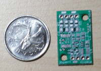
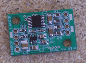
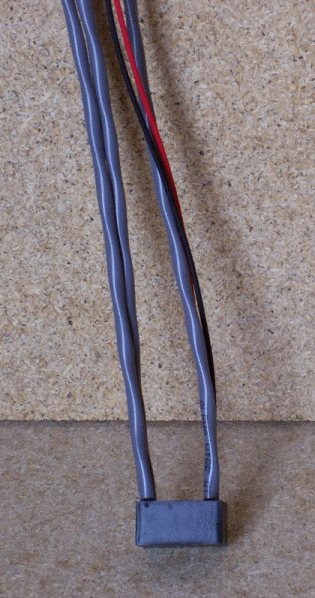
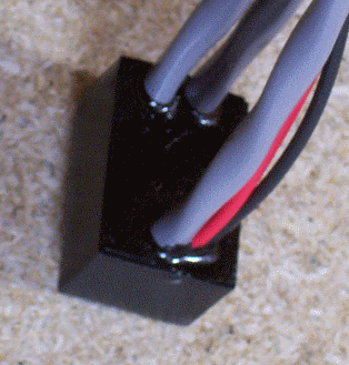
The board is available either as an assembled board to be put inside the ECU (or another case) using the mounting holes or as an external device potted in its own box with pigtail wires. The pictures below show the unpopulated board (that's a Canadian quarter besides the board), the populated board, the external box with pigtails and a close up of the potted board. The external version has shielded wires for both the inputs (2 wires per VR sensor)and outputs (one shielded pair for bot outputs) and a 12V and ground wire. The shields are grounded at the board so there won't be a need to ground it somewhere else or to connect the shield to a connector.

The web page to order them will be available shortly. It should be noted that I will no longer carry the V1 dual VR board (LM1819-based board) since there are other alternatives for this circuit.

Jean

Image Image Image Image
jbperf.com Main site . . . . . . . . . . . . . . . . . . . . . . jbperf.com Forum
Image
Poolside
Helpful MS/Extra'er
Posts: 85
Joined: Sun Aug 22, 2004 6:01 pm
Location: Long Beach CA

Re: New dual VR board V2.0

Post by Poolside »

Looks like another solid winner Jean. Good job!

- Jim
chense
Helpful MS/Extra'er
Posts: 92
Joined: Sat Jun 17, 2006 7:11 am
Location: Zagreb, Croatia

Re: New dual VR board V2.0

Post by chense »

Amazing!

So now I can have the crank and cam VR conditioners in the harness, and just feed the MS with square trigger signal, keeping those fragile signals away from power electronics :mrgreen: .

Since the MS already has filtered 5V PS, can you provide an extra +5V wire in the packaged version (I would feel more confident using the +5V MS power supply, since it's heavily filtered (at least mine 8) ) and already in the harness)?

Another (nitpicky) note - for in-harness mounting, it would help if the overall thickness of the whole thing is smaller, so there isn't a big lump in the harness. Routing the wires through the sides of the case would do the trick.


--
Bye,
Tom
elaw
Super MS/Extra'er
Posts: 2926
Joined: Fri Oct 16, 2009 6:20 am
Location: Wilmington, MA

Re: New dual VR board V2.0

Post by elaw »

Jean,

That's very cool! Although I agree with Chense that it would be nice to have the wires coming off the ends of the board rather than perpendicular. I bet that would make potting a lot harder though.

Now all you have to do is integrate the wheel translator into this design :mrgreen:
Eric Law
1990 Audi 80 quattro with AAN turbo engine: happily running on MS3+MS3X
2012 Audi A4 quattro, desperately in need of tweaking

Be alert! America needs more lerts.
racingmini_mtl
Super MS/Extra'er
Posts: 9130
Joined: Sun May 02, 2004 6:51 am
Location: Quebec, Canada
Contact:

Re: New dual VR board V2.0

Post by racingmini_mtl »

My initial thought was to have the wires come out the sides also but it's not that easy and, yes, would make potting harder. I will look at it again but I can't just drill holes since I wouldn't be able to feed the wires and install the board. It would have to be slots from the top.

As for the supply, with the board size, there isn't much place for options so using the MS 5V would require a custom build which I'm not planning at this time. However, remember that the 5V square wave output is a digital signal input to the MS so it doesn't need to be that stable (not that I think it will be unstable). The issue with this type of signal is more likely to come from noise induced in the wires which is why I use shielded wires for both inputs and outputs to avoid it.

Having said that, the voltage regulator I use is a low dropout regulator with a voltage dropout of less than 400mV and the VR conditioner chip is rated from 4.5V so you could simply use your MS 5V supply instead of the 12V input and it would work even though you'd have a signal output of about 4.5V amplitude which is still much more than what is needed by the MS CPU.

And Eric, I've thought of it. And depending on what happens with the current design, that could happen. The CPU I use is available in a surface mount package...

Jean
jbperf.com Main site . . . . . . . . . . . . . . . . . . . . . . jbperf.com Forum
Image
elaw
Super MS/Extra'er
Posts: 2926
Joined: Fri Oct 16, 2009 6:20 am
Location: Wilmington, MA

Re: New dual VR board V2.0

Post by elaw »

Hey here's a goofy idea that might work depending on the PCB dimensions...

Buy any cheap automotive relay with a mounting tab molded into the case (like this one: http://www.amazon.com/VDC-Automotive-Re ... B0002KR9GG). Remove the guts from the relay and pot your assembled board into it. You'd end up with an easy-to-mount little module with the wires coming out the bottom for protection against water entry.
Eric Law
1990 Audi 80 quattro with AAN turbo engine: happily running on MS3+MS3X
2012 Audi A4 quattro, desperately in need of tweaking

Be alert! America needs more lerts.
racingmini_mtl
Super MS/Extra'er
Posts: 9130
Joined: Sun May 02, 2004 6:51 am
Location: Quebec, Canada
Contact:

Re: New dual VR board V2.0

Post by racingmini_mtl »

It's not a bad idea but I'm not sure if the size would match. Also, you can pretty much do the same thing with what I have now by simply using a metal bracket or a metal strap around the case and between the input and output wires (if you see what I mean from the pictures). Then you can have the wires either coming up or down depending on the location of the bracket and the rest of the wiring loom.

And with the potting, I'm not worried about water (or any other fluid or dirt) with the box in any position. The only place where you might want to do something about it is at the connector you'll install on the pigtails and that will depend on the connector(s) chosen.

Jean
jbperf.com Main site . . . . . . . . . . . . . . . . . . . . . . jbperf.com Forum
Image
Poolside
Helpful MS/Extra'er
Posts: 85
Joined: Sun Aug 22, 2004 6:01 pm
Location: Long Beach CA

Re: New dual VR board V2.0

Post by Poolside »

About the 5V output signal and noise, a bigger issue might be an underdamped signal, 'reflection' or 'ringing'. Those things can happen if the signal transition time (slew rate) is quicker than the signal transmission time. For a long transmission line, a fast slew rate causes ringing.

- Jim
mike_robert
Helpful MS/Extra'er
Posts: 139
Joined: Sun Feb 10, 2008 8:26 am

Re: New dual VR board V2.0

Post by mike_robert »

Jim/Poolside, question:
If one has 10 feet between the VR sensor and the ECU, it's better to have
1) VR sensor->9' cable (carrying VR analog signal)->zero crossing detector->1' cable (carrying square wave)-> ECU
rather than
2) VR sensor->1' cable (carrying VR analog signal)->zero crossing detector->9' cable (carrying square wave)-> ECU, correct?

If we need a new thread for this, I apologize. BTW, Jean, what chip are you using for the 2.0 board? I'd like to look at the datasheet.

-Mike
racingmini_mtl
Super MS/Extra'er
Posts: 9130
Joined: Sun May 02, 2004 6:51 am
Location: Quebec, Canada
Contact:

Re: New dual VR board V2.0

Post by racingmini_mtl »

This is based on the MAX9926 (datasheet: http://datasheets.maxim-ic.com/en/ds/MA ... AX9927.pdf). And by the way, there are 2 of these on the I/O Extender.

Jean
jbperf.com Main site . . . . . . . . . . . . . . . . . . . . . . jbperf.com Forum
Image
johnc32779
Experienced MS/Extra'er
Posts: 163
Joined: Wed May 05, 2004 7:17 pm
Location: Longwood, Florida

Re: New dual VR board V2.0

Post by johnc32779 »

Jean, what is the maximum input voltage, and minimum trigger voltage, for your new dual VR board?
BMW 1971 E3 Sedan; 1989 E34 M30 Engine, 60-2; 5spd-OD
racingmini_mtl
Super MS/Extra'er
Posts: 9130
Joined: Sun May 02, 2004 6:51 am
Location: Quebec, Canada
Contact:

Re: New dual VR board V2.0

Post by racingmini_mtl »

The maximum input voltage should be more than 150V (and likely up to 250V) and the minimum trigger voltage should be less than 100mV and this is an adaptive threshold. So that should cover pretty much all available sensors.

I haven't tested those limits but this comes from the data sheet and the components I use.

Jean
jbperf.com Main site . . . . . . . . . . . . . . . . . . . . . . jbperf.com Forum
Image
johnc32779
Experienced MS/Extra'er
Posts: 163
Joined: Wed May 05, 2004 7:17 pm
Location: Longwood, Florida

Re: New dual VR board V2.0

Post by johnc32779 »

Thank you for the prompt reply. I don't know what my maximum VR voltage is, but I suspect quite high. I recall seeing 200 volts, but I don't recall whether that was peak to peak AC or what. Also I don't recall the the RPM, but I am confident it wasn't near maximum. Since the voltage could exceed the rating of my scope, I am thinking a AC multimeter reading should be reasonably accurate since the signal is somewhat sinusoidal.

I assume you have internal clamping on the IC input, so I assume the maximum input set by of power dissipation -- correct?
BMW 1971 E3 Sedan; 1989 E34 M30 Engine, 60-2; 5spd-OD
racingmini_mtl
Super MS/Extra'er
Posts: 9130
Joined: Sun May 02, 2004 6:51 am
Location: Quebec, Canada
Contact:

Re: New dual VR board V2.0

Post by racingmini_mtl »

johnc32779 wrote:I assume you have internal clamping on the IC input, so I assume the maximum input set by of power dissipation -- correct?
Correct.
jbperf.com Main site . . . . . . . . . . . . . . . . . . . . . . jbperf.com Forum
Image
miklec
Helpful MS/Extra'er
Posts: 52
Joined: Thu Apr 03, 2008 8:04 pm

Re: New dual VR board V2.0

Post by miklec »

Jean,

I have been chasing a VR problem for a while. I believe it is due to 2 processors sharing the VR sensor. I can get the old 1.1 board to fire to redline but then the OE PCM throws a code due to weak signal. I did this by increasing R2 to 1K. When R2 was left open the factory PCM worked fine, but I experienced cut-outs above 5200 RPM. I was wondering if your new VR conditioner would do better to not be paracytic on the VR signal. The other option would be to build a circuit from an earlier post. The writer did not give the model number of the Op-Amp involved. The Op-Amp and associated components could be wired then tied to the Existing board input. Better yet, a new board could be engineered to allow for the isolated option. I am sure as time goes on the need to share signals will increase as modern PCMs control much more than fuel and spark. Some other devices such as data loggers use the same signal as well. Any thoughts on the subject would be welcomed.

Warm Regards,
Mike
racingmini_mtl
Super MS/Extra'er
Posts: 9130
Joined: Sun May 02, 2004 6:51 am
Location: Quebec, Canada
Contact:

Re: New dual VR board V2.0

Post by racingmini_mtl »

Mike,

I have not tested the new board with the sensor connected in parallel with the OEM ECU and I'm not setup to make the test either. But since the new board has differential inputs and actually have an internal op-amp on its inputs, it might work. And since it is more sensitive and has an adaptive threshold it might be possible to use larger resistors at the input if the signal is not strong enough for the OEM ECU.

But someone will have to test that with the current design (either the dual VR board V2.0 or the I/O Extender). And if there is still a need for an additional op-amp and there is enough demand for it, I'll see what can be done.

Jean
jbperf.com Main site . . . . . . . . . . . . . . . . . . . . . . jbperf.com Forum
Image
h22
Helpful MS/Extra'er
Posts: 107
Joined: Wed May 27, 2009 12:05 pm

Re: New dual VR board V2.0

Post by h22 »

Mike,

I have not tested the new board with the sensor connected in parallel with the OEM ECU and I'm not setup to make the test either. But since the new board has differential inputs and actually have an internal op-amp on its inputs, it might work. And since it is more sensitive and has an adaptive threshold it might be possible to use larger resistors at the input if the signal is not strong enough for the OEM ECU.

But someone will have to test that with the current design (either the dual VR board V2.0 or the I/O Extender). And if there is still a need for an additional op-amp and there is enough demand for it, I'll see what can be done.
Jean, I am currently building an adapter board that will allow me to run an MS2 daughter card on my bike, basically plag and play.
You pointed me to the MAX9926 chip when I asked about it from the I/O extender board that you are sending me.
My current PCB is designed with the basic LM1815 on it, but due to space limmitations the MAX2294 ( single version) looks like a real winner. I As I will be piggy backing this with the stock ECM for initial tuning and testing, I could offer feedback on how it works sharing the VR signal.

The MAX9924-7 spec sheet lislt several modes of operation, with the 94&96 offering the use of external resistors ( in lew of pre set internal ones ) for the internal op-amp, thus allowing the user to set the gain ( hope I have that right ). I am curious what " MODE" you have elected to use this chip in (schem would be nice....). I was going to just use the supplied example of mode A1 or A2 ( leaning twards A2, I dont see an an advantage for using A1...corect me if I am wrong) .

As My bike only has 1 sensor, no need for more than 1 circuit, and if I do add a cam sensor it will most likely be a hall effect triggering the MS through an opto.
Joe
h22
Helpful MS/Extra'er
Posts: 107
Joined: Wed May 27, 2009 12:05 pm

Re: New dual VR board V2.0

Post by h22 »

Just guessing here, but looking at that tiny pic it appears you are operating it in mode A2, the 4 resistors on the right are VR input, and the two on the left are output pull-ups?

My board is still a week or two away from being finalized and sent out to be made. So I may play around with the design a bit & see if I can make room for the additional components and jumpers to try different modes.
racingmini_mtl
Super MS/Extra'er
Posts: 9130
Joined: Sun May 02, 2004 6:51 am
Location: Quebec, Canada
Contact:

Re: New dual VR board V2.0

Post by racingmini_mtl »

The advantage of A1 and A2 is that they are using the adaptive threshold with A2 using the internal reference. So until I get some feedback that this is not satisfactory, I'll be using A2. It's already flexible enough to allow a 0-5V signal from a Hall or opto sensor to be used which is more than what can be done with an LM1815.

Jean
jbperf.com Main site . . . . . . . . . . . . . . . . . . . . . . jbperf.com Forum
Image
Joe Perez
Experienced MS/Extra'er
Posts: 181
Joined: Mon Dec 03, 2007 2:19 pm
Location: San Diego, CA
Contact:

Re: New dual VR board V2.0

Post by Joe Perez »

I recently built a new VR decoder for myself using the MAX9924. Basically just an exact copy of the mode A2 reference schematic, with a few extra caps thrown in across the power supply. (I think I had a 1μf and a 33μf lying around at the time.)

It's wonderful!

Previously, I'd tried the 1815, and had problems with it missing teeth. The teeth on my laser-cut wheel aren't all perfectly the same height, so couple that with engine vibration causing the sensor to move a little, and you get large differences in amplitude from one tooth to the next.

I've been using the stock 3.0 schematic (on a seperate board) for a couple years, and it's ok, but I still got a very occasional miss now and then.

The 9924, by comparison, seems almost magical. I've got some scope traces saved on my laptop at home, but basically when I was bench-testing it (by waving a screwdriver in front of the sensor) I found that it did an excellent job of recovering a signal from extremely dirty inputs, even with massive variations in amplitude from one to the next, and with incoming signals down to a few tens of millivolts. I'm running it with about 3mm sensor gap right now (I just eyeballed it- no feeler gauges), and it's just rock-solid.

Heck, the differential input alone is enough to make me love it. Hurrah for balanced signals. :mrgreen:
Post Reply